
<< 2 Safe System of Work | Table of Contents | 4 Reasonable Measures for Working near Underground Electricity Cables >>
3 Reasonable Steps for Working near Underground Electricity Cables
The reasonable steps to a safe system of work for works near U/G cables begin at the design stage and involve the early participation of the electricity supplier. Once cable plans have been received from the supplier, a competent person is appointed to detect the alignment of the U/G cables and propose trial hole locations. Working closely with site personnel, the competent person helps to open trial holes and expose cables to allow their alignment and depth to be accurately ascertained. He then prepares the "Competent Person Written Report" and clearly marks up cable alignment and depth on site.
3.1 Plans from electricity supplier
3.2 Locating U/G cable alignment (passive detection)
3.3 Trial holes (exposing cable and active detection)
3.4 Competent person written report
3.1 Plans from electricity supplier
3.1.1 The working party shall approach electricity supplier for information and cable plans before any works begin, except for works which involve only minor shallow excavation9.
3.1.2 An early approach to the electricity supplier is particularly recommended for a major project involving large scale construction or horizontal drilling or tunnelling. Consideration should be given at the design stage, as early as the feasibility study, to planning works away from the vicinity of existing U/G cables. If a major diversion of U/G cables is necessary, the electricity supplier may require a long lead time to plan and complete the diversion.
3.1.3 The request for information made to the electricity supplier should include a full description of the scope and, where appropriate, the nature of the proposed works. The electricity supplier can then identify the area over which it considers its U/G cables may be affected and provide all available records of U/G cables in the vicinity.
3.1.4 Upon receiving written notice of proposed works from a working party, the electricity supplier shall without charge provide the cable plans of the proposed works site or its vicinity within 14 working days or such period as is mutually agreed between the concerned parties.

3.1.5 The date of commencement of the time period stipulated above (in 3.1.4) is the date upon which the electricity supplier received and date-stamped the notice. Notices shall be immediately date-stamped when they are received by the electricity supplier and retained for a minimum of five years. The working party may request, in the notice, an acknowledgment of its receipt, stating the date upon which it was received.
3.1.6 The working party shall consult or request new cable plans from the electricity supplier 14 working days before commencement of works, if the plans in hand have been provided for more than three months. After commencement of works, if the working party has overall control of the works site until completion of the works, the requisition of new cable plans is not necessary unless the working party has given access to the electricity supplier for laying new cables.
3.1.7 The cable plans10 provided by the electricity supplier shall be of suitable scale sufficient for the working party to identify the following cable information:
(a) number of cables including abandoned cables;
(b) their respective voltage rating and size;
(c) their alignment, with dimensions making reference to appropriate reference points; and
(d) any shallow cover locations (i.e. cables with buried depth less than 900 mm in a carriageway or 450 mm in other areas), to the best of the electricity supplier’s knowledge.
3.1.8 Cable plans provided by the electricity supplier provide a good indication of the presence and alignment of U/G cables at a particular site, and will help subsequent cable detection. However, it should be noted that the accuracy of plans cannot be relied upon fully because:
Back to Top(a) the position of reference points (e.g. the kerb or building line) may have been moved since the plans were drawn;
(b) regrading or resurfacing of the road may mean that the depth shown, if provided, are now incorrect;
(c) U/G cables may have been moved without the authorization or knowledge of the electricity supplier;
(d) U/G cables, marked as straight lines may not, in practice, run in a straight alignment; and
(e) the level and alignment of U/G cables may change sharply over a short distance due to the presence of underground obstructions.
3.2 Locating U/G cable alignment (passive detection)
3.2.1 The working party shall decide whether the works site is within the vicinity
of U/G cables in accordance with the distance specified in Table 1 (i.e. Section
1.3.2.5). If the cable plans supplied by the electricity supplier indicate that
there are U/G cables within the works site and/or the area of the specified
distance from the works site, the working party shall appoint a competent
person to carry out the cable detection work.
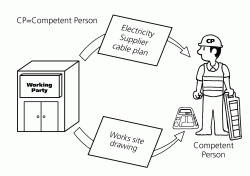
3.2.2 Before the cable detection takes place, the competent person shall be
provided with electricity supplier’s cable plans and works site drawings.
The cable detection device to be used by the competent person shall be non-destructive
and calibrated as per the manufacturer’s requirements. In the course of cable
detection, the competent person shall repeatedly refer to the cable plans to
pinpoint as accurately as possible the alignment of any U/G cables.
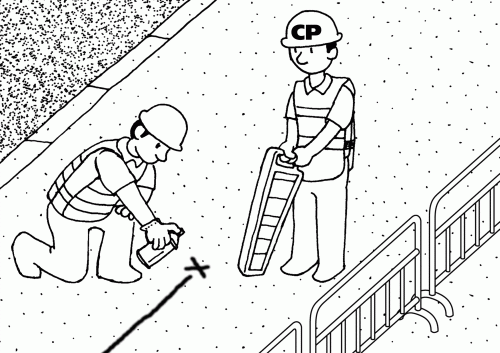
3.2.3 Under normal conditions, the competent person should select the 50Hz
passive detection mode of the cable detection device for alignment
detection. The larger the 50Hz unbalanced current (i.e. the vector sum of the
currents in phase conductors is not zero) flowing in the cable gives a stronger
signal, allowing the competent person to locate the most probable alignment
of each U/G cable. However, depth measurement from this detection mode is not
accurate and should not be relied upon.
3.2.4 It should be noted that 50Hz passive detection cannot detect the existence
of de-energized U/G cables, energized U/G cables with no load and current-balanced
U/G cables. If the cable alignment cannot be detected by means
of 50Hz passive detection, the competent person can switch to the following
alternative detections:
(a) Radio frequency passive detection – Another passive mode selected at the cable detection device, this method provides less definite alignment detection than 50Hz passive detection because other utilities with metallic objects may also re-emit the radio frequency signal.
(b) Inductive detection – This detection mode requires the use of a signal generator (the transmitter) and a separate receiver. This method can only be used when certain part of the U/G cable alignment is accurately known so that the transmitter can be properly positioned right above it. It should be noted that the accuracy of this method is very much affected by other utilities with metallic objects close to the target cable.
3.2.5 The competent person should be able to detect the most probable alignment
of the U/G cables identified on the cable plans if the current-carrying cables
are properly laid out with an adequate horizontal clearance. However, if the
U/G cables are very close to each other or crossing each other or laid in different
layers (e.g. cables in the same alignment but at different depths), the competent
person will not be able to detect the most probable alignment for each U/G cable.
Instead, he can locate a peak signal for the group of U/G cables
and record its alignment and note the number and voltage level of the cables
that it may represent.
3.2.6 The competent person is required to note in writing the existence of any
U/G cable at the works site or its vicinity and any identified U/G cable alignment.
This written record shall bear the heading "Cable Alignment Record"
and include the following details:
(a) name and approval number of competent person;
(b) name of the working party or site contractor;
(c) location, date and time for which the work on locating the U/G cable alignment was carried out;
(d) U/G cable alignment (for each U/G cable or for each group of cables) based on common reference points (e.g. lamp pole, traffic light post or hydrant, etc.)
(e) brand name, model number, serial number, calibration record and mode of operation of the U/G cable detection device used for the detection;
(f) proposed trial hole locations; and
(g) photos showing site markings for cable alignment.
3.2.7 The competent person shall propose trial hole locations according to the detected alignment or, in case the alignment cannot be located due to de-energized or current-balanced cables, by referring to the electricity supplier’s cable plans. The proposed locations at appropriate intervals shall be, as far as practicable, convenient for the working party to expose as many U/G cables as possible for the purpose of toroidal active detection as described in Section 3.3.1 (b).
3.2.8 The competent person is responsible for marking the alignment at the location and its vicinity where the trial hole is to be opened. This marking should be done with waterproof crayon, paint or self-adhesive temporary road marking tapes on paved surfaces, or with wooden pegs in grass or unpaved areas.
3.2.9 The competent person should brief the working party on the content of the cable alignment record, with particular reference to the locations of the proposed trial hole opening and the number of target U/G cables to be exposed.
3.2.10 In case of a minor shallow excavation, the competent person shall mark the cable alignment, if any, within and in the vicinity of the works site and submit the Cable Alignment Record as a Competent Person Written Report to the working party appointing him.
3.3 Trial holes (exposing cable and active detection)
3.3.1 The working party shall proceed with the following reasonable steps except for works which involve only minor shallow excavation:
(a) Trial hole Excavation – Great caution has to be exercised when exposing the target U/G cable. The excavation of the trial hole shall be supervised by the competent person who should repeatedly use a cable detection device and frequently update the working personnel as to the most accurate cable location until the target cable is exposed.
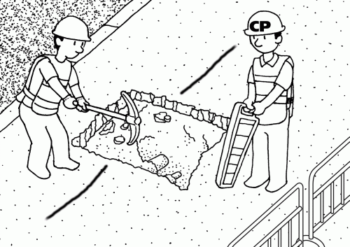
(b) Toroidal active detection - The target cable inside the trial hole is adequately exposed so as to permit the competent person to place a signal clamp around it. A known high frequency signal is injected into the cable by electromagnetic induction through the signal clamp. As only the target cable carries this high frequency signal, the competent person can use a receiver selected to this signal frequency to detect at appropriate interval (say, 1-3m) the alignment and depth of the unexposed part of the target U/G cable, starting from the trial hole.

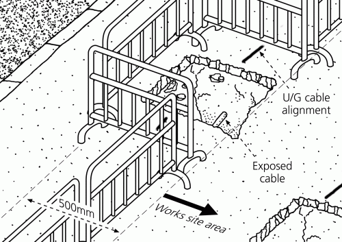
3.3.2 Trial hole excavation shall be carried out when:
(a) the alignment of any U/G cable is ascertained to be within the works site and/or within the area 500mm away from the boundary of the works site, or;
(b) the alignment of any peak signals for a group of U/G cables is located within the works site and/or within the area 3m away from the boundary of the works site.
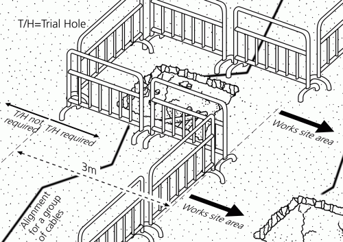
3.3.3 As to 3.3.2 (b), if the alignment of the peak signals is located between
the area 500mm and 3m away from the works site and it is not practicable
to open trial hole within that area (e.g. the works site is at a footpath
whereas the alignment is located at a carriageway), the competent person should
propose the following:
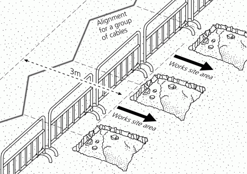
(a) open a number of trial holes along the boundary of the works site opposite the alignment of the peak signals. The competent person shall determine the number of trial holes based on the alignment and the number of cables within the group. In principle, the closer the alignment and/or the greater the number of cables within the group, the more trial holes will be required.
(b) The trial holes should be proposed at the locations where the peak signals are closest to the works site.
(c) The trial hole should be excavated at a right angle to the alignment and extended 500mm away from the works site.
(d) The alignment and depth of any cables found in the trial holes shall be ascertained by means of toroidal active detection.
3.3.4 Before beginning trial hole excavation, the working party shall inform
the electricity supplier of the nature of the intended works if:
(a) the target cables are of 132kV or above; or
(b) the works involve trenchless excavation or horizontal drilling such as tunnelling, percussion moling, pipe jacking and soil nailing, etc.
The electricity supplier may deem the excavation of a trial hole unnecessary if the works involved are below ground level, where U/G cables would not be affected or where U/G cables do not exist. Any agreement between the electricity supplier and the working party shall be properly signed and recorded for inspection upon request by EMSD.
3.3.5 If the works site is not large but heavily congested with many U/G cables and/or other utilities (e.g. in a rear lane), the competent person may consider supervising the excavation until all U/G cables are exposed within the works site.
3.3.6 If the competent person encounters genuine difficulty in locating the U/G cables shown in the electricity supplier’s plans, he shall seek necessary assistance from the electricity supplier. The electricity supplier shall send technical staff to the site, not more than three working days after receipt of the request, to assist with locating U/G cables as necessary without charge.
3.3.7 Should there be any doubt regarding discrepancies between the cable detection results and the electricity supplier’s cable plans, the competent person shall repeat the cable detection and/or contact electricity supplier for clarification on site.
3.4 Competent person written report
3.4.1 Upon completion of active cable detection, the competent person is required to prepare a proper record form for submission to the working party appointing him. The form shall bear the heading "Competent Person Written Report" and include the following details:
(a) name and approval number of competent person;
(b) name of the working party or site contractor;
(c) location, date and time for which the active detection was carried out;
(d) the cable layout plan detailing the alignment of each U/G cable based on common reference points (e.g. lamp pole, traffic light post, or hydrant, etc.) and any cable sections in shallow depth;
(Note: a cable alignment band can be used to represent a group of U/G cables of which the ascertained alignment are very close to each other. The alignment and size of the band shall be dimensioned and the number of U/G cables that the band represents shall be specified.)(e) depth profile of each U/G cable (i.e. cable depth corresponding to each measurement point along the cable alignment);
(f) voltage level of each U/G cable;
(g) electricity supplier’s advice, if any;
(h) photos showing the toroidal active detection and site markings for cable alignment and depth; and
(i) brand name, model number, serial number, calibration record and the adopted frequency of the U/G cable detection device used for the detection.
3.4.2 The working party shall provide the site personnel with a copy of the Competent Person Written Report. In addition, the working party should arrange a site briefing given by the competent person to ensure that the site personnel are conversant with the contents of the Report and aware of the required safety precautions.
3.4.3 The working party should ensure that the Competent Person Written Report is available for inspection, upon request by the Director until the works are completed without occurrence of any cable damage.
3.4.4 The competent person is responsible for marking the alignment and depth of all U/G cables with waterproof crayon, paint or self-adhesive temporary road marking tapes on paved surfaces or with wooden pegs in grass or unpaved areas. Steel pins, spikes or long pegs, which could damage U/G cables laid at shallow depth, must not be used. Any section of the U/G cable with a sudden reduction of buried depth shall be clearly marked along the alignment.
3.4.5 The working party shall ensure that the markings (both alignment and depth) identified by the competent person are available at site before the commencement of works. After completion of the works, the working party should erase any residual markings on paved surfaces and not deface any traffic marking signs. To avoid confusion to drivers, markings in carriageways should only be laid after the area is fenced off from traffic. Such markings should be completely removed before the area is re-opened to traffic.
9 See Definition in Section 1.3.2.3 [Go Back]
10 Information on depth of U/G cable is not generally available in the electricity supplier’s cable plans. Normally the electricity suppliers install new cables according to the buried depth shown in Table 2 of Appendix 3. [Go Back]